Click here for Schmidt Plows
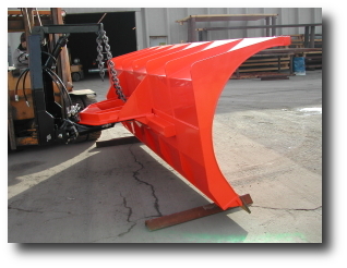
JENSEN™ Highway PlowsAvailable in 10-12 foot lengths.
3-Way Power = RIGHT / LEFT / UP / GRAVITY DOWN
Large Plow Detail Specifications
Moldboard
3/16" thick and approximately 41" high with 8" cutting edge attached.
Smooth formed with integral extension similar to moldboard contour. The "mailbox" cut-out on the top of moldboard (shown) is an option.
½" thick by 12" wide, 4 cord minimum rubber belting shield. Rubber shield is to be bolted to the moldboard in approximately a 45 ° position, with reinforcement bar across the front for strength. The bars are strong enough not to bend in normal operation of the plow.
8 ea. one-piece ribs are 2" - 3½" wide and 1/2" thick. The ribs are one-piece with no weld joints, and run from top to bottom of moldboard. Where the rib is fastened at the top, the bottom of the rib is cut to allow water to drain. The ribs have continuous welds.
Angle attachment of moldboard at the bottom is accomplished using a "Z" design. The angle is 4" x 2" x 4" material. Both flange edges of angle are welded continuously to the back side of moldboard with a 2"x4" flat bar under the angle on moldboard with continuous welds. Gussets are welded to bottom side of angle every 12" -18". The angle is enclosed at each end.
Cutting Edge
Cutting edges come installed. Steel is high grade, open-hearth, basic oxygen or electric furnace steel of the following chemistry:
Carbon .80 to .93
Manganese .60 to .90

Sulphur .50 Max.
Phosphorous .40 Max.
Silicone .15 to .30
Mechanical property; Brinell hardness 255-321
Blade dimension = ¾" x 8" x 72" - 2 ea..
Center holes in line with 1/16" of established center line.
Limits and tolerances unless otherwise specified not to exceed 1/16".
Safety Trip
Two single heavy compression spring trip. Spring has provisions for adjustment of cutting angle; this includes 12° to 24° back from vertical. The springs have strength to hold the plow at position within 1" from adjusted setting when full weight of plow is on edges and pushed forward.
There are rubber stops that keep the plow from full tripping.
Push Beam
Push beam is 4"x4"x3/8" minimum square tube, to be long enough to fasten to at least five each of the vertical ribs. The beam is attached to the moldboard in at least 5 places, two of which are at the ends of the beam. The attachments are made on the ribs of the moldboard. The ribs are reinforced at attached points. There are no holes in square tubing for any mounting purpose. There are 1" machined, zinc plated push pivot pins that attach push frame to moldboard. Attachment points of the push beam to moldboard and trip springs to moldboard and vertical ribs are built-up. Build-up is 1" thick around drilled holes. Extra plates are welded on all sides with solid welds.
Reversing Frame
Frame and reversing circle is constructed of 4"x4"x3/4" minimum; angle or formed plate.
Level Lift
Plow is a "level lift" design. If level lift requires chains, chains are 1/2" grade 70 and attached with clevis chain attachments instead of cold shunts. ¾" clevis through center rib, if there is only one center (6 to 8 inches from top of plow) for handling plow during repair work.
Reversing Cylinders
2 ea. double acting, 4" bore x10" stroke with "Cap T" seals, 2" diameter chrome plated or nitrated rod with 1/2" pipe threaded ports required. 45° swivels on back ends of cylinder, 90° pipe swivels on front ports only. No hole allowed in shaft for mounting purposes. The size and capacity are proven adequate for the design of the reversing hardware.
Cylinder Mounting
Cylinders are mounted on bottom of turntable and are arranged to allow access to top and bottom of both pins so the cylinder can be easily replaced in the field by pulling pins without any disassembly of reversing frame AND without removing plow from truck.
Hydraulics
Hoses are located above frame and clamped in place to prevent damage. Connecting hoses are 1/2", number 8 SAE 100R2 with Parker FF-501-8FP quick coupling for right angle; and Parker FF-502-8FP quick coupling for left angle. Quick couplers have dust caps. Hoses are routed to the right side of frame. Hoses reach 36" beyond right attaching ear. Crossover relief valve is Gresen 3100 F (or equivalent) with 1/2" ports at 30 gpm and mounted so as not to interfere with plow operation.
Running Gear
No shoes or wheels required. Adjustable parking jack on circle frame to allow easy mounting of plow to truck. Jacks are removed and stored in truck during plow operation.
Plow Angle
The frame and cylinders provide a minimum plow angle of 40° each side of center. There are stops on the turning circle welded sufficiently to hold the plow at 40° while keeping the plow from bottoming. When cylinder is fully angled, cylinder stroke is limited to 1/2" less than full stroke.
Weight
Weight of the complete plow, including cylinders and cutting edges is 1700 lb – 2000 lbs.
Identification
Each unit has a metal tag permanently attached approximately 3" in from the second rib on the upper right corner on the back of the shell, with the following data:
Manufacturer’s name, year, model number and serial number. Numbers are 2" high and are placed below the manufacturer’s tag. The unit number is applied by welding numbers on a flat bar.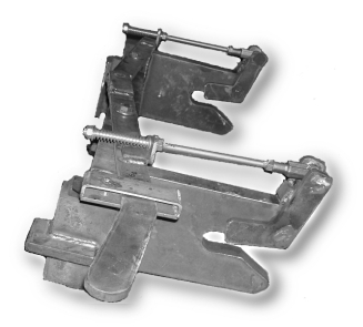
Attachment
Plow hitch is a universal Quick-Hitch™. The hitch is attached to the circle frame in a manor to maintain the circle at or near horizontal positioning when attached to truck receiver. Receiver locking pin is 16" to center above ground level. Attaching ears protrude 4" into the receiver and hook to the pin. Distance between ears is 27 1/2" minimum.
For an Owner Operators & Parts Manual, click here.
For information on the PolarFlex blade system, click here.

If you can't open this document, click on this imagefor a free download.
We also have Schmidt highway plows. Click here !


Back
Holland Equipment Co. 2870 West 2100 South - SLC, UT 84119 - (801) 972-1601 - (800) 234-8611 - FAX (801) 972-6730
HOME